 Simplified Inverter Notation
Beyond power sources, transmission dust, and devices, there is a fourth category of redstone circuitry in Minecraft PE: The inverter. In addition to using an inverter to negate a signal, you can also put them together to make repeaters, clocks, and more complicated stuff. Unfortunately, an inverter isn't a single block, but a combination of three blocks (usually). Furthermore, one of those blocks is "any" solid block, including dirt, and another is a redstone torch which is supposed to be a power source, so it all looks non-intuitive. Start putting inverters together and the whole circuit looks like "voodoo magic."
If you search the web there exists "standard" redstone circuit diagram symbols, which does help you reproduce the circuit but does very little to help you understand how it works. We need a better way to represent circuits so you can analyze and design circuits more quickly and intuitively.
Inverter, Type B-B:
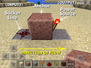
This inverter is the simplest to understand
as all three blocks are on the same level (elevation). Here are the three components
of it:

Application: Repeater: What can you do with inverters besides just turn an on/off switch into an off/on switch? One simple application is the repeater. If you invert something twice, you are back to where you started. But since each inverter has its own power source, you are starting again at full strength. In the picture below, you can see that the restone dust grows dimmer the farther away you get from the switch (which, interestingly, happens to be a power source in its own right). The maximum length is 15. With the repeater (made up of two inverters), the signal is "repeated" and you can extend the length to power the redstone lamp. NOTE: The two inverters introduce a slight (0.2 second) delay from when the switch is thrown to when the lamp changes state.

Inverter, Type B-B, bent variation: This is the same B-B inverter but with the third block off in a different direction; it works exactly the same way.


Application: Basic Five Clock Using Only B-B Inverters: In the previous application, we used an EVEN number of inverters to create a repeater. What happens if we use an ODD number, then connect them around in a loop? Starting with power ON, the first inverter turns it OFF, then the next one ON, then the next one OFF, then the next one ON. Connecting back to the first one, the ON state forces the output back OFF. Then it's ON, OFF, ON, OFF, then the OFF state forces the first inverter back ON again. The whole thing is unstable, and the torches blink on and off. We've created a blinking circuit, known in the electronics world as a CLOCK because the torches blink at a consistent rate. The speed of the blink is dependent on the number of inverters because each one introduces a 0.1 second delay. You can make a clock with one inverter or three inverters, but this is not recommended because if the torches blink too fast they will "burn out" temporarily. So use 5 or more torches. Since all the torches blink at the same rate, you can attach an output, like a redstone lamp, at any convenient point in the loop (as shown). The lamp now blinks ON and OFF!


Inverter, Type B-T: If we allow circuits on two levels (layers) instead of one, we can stack the anchor and redstone torch blocks to make a more compact inverter. Note that this puts the power source on TOP (T), so the next inverter or other component will need to be on TOP (T) also.


Inverter, Type T-B: This is the reverse of the B-T inverter, created by stacking the sucker line and anchor blocks. The sucker line will need to get its power from a TOP (T) block, such as a B-T inverter.


Inverter, Type T-T: This is created simply by moving a B-B inverter to the top level. The sucker line will need to get its power from a TOP (T) block.


Inverter, Type B-BT: This is a special variant of the B-B inverter. According to one of the weird rules, if a solid block is placed above the torch, then both the torch and the solid block become power sources. Yes, the solid block can even power adjacent redstone dust. We use the "BT" terminology to indicate that there is power on both levels. The next inverter can have either a T sucker line or B sucker line. Be careful with B-BT as the double power source could accidentally light up redstone dust on a parallel circuit on either level.


Inverter, Type T: This strange inverter is just a lone torch on the top (T) level with no sucker line nor anchor. The T inverter MUST be anchored, then, on an adjacent B-BT inverter. The special powered block of the B-BT inverter serves as the anchor, and no sucker line is needed due to the B-BT's torch directly underneath. The reason we don't consider the special powered block part of the T inverter is because the B-BT doesn't have to power a T inverter; it can be a T-B inverter with the special powered block lighting up the T-B's sucker line. So we represent the T inverter as a single block.


Compact Five Clock #1: Now that the inverter variations have been introduced, we can construct a five clock that takes up a lot less space. At a casual glance, it looks like a random mix, but once you identify the inverters, it all makes perfect sense. Notice how all the inverters match up: always B next to B and T next to T. Also, because parallel circuits are next to each other, we made sure that sucker lines from the first row don't touch power sources on the second row and vice versa.


Notice the solid block in the upper-left is optional. It's not part of the T inverter which consists of a torch only. The extra block merely adds clarity (that the signal is on the second level). Without it (above, right), it looks like more "voodoo magic" since it appears that the next inverter's sucker line gets its power "from the air". It's from the torch, of course, which is directly adjacent, but at a very casual glance it doesn't LOOK adjacent. Looking at the circuit diagram, though, it all makes perfect sense.
In the final screenshot above, a redstone lamp is connected, which blinks on and off. Note that the lamp can be attached to ANY convenient part of the five clock where it can get power.
Compact Five Clock #2: With the introduction of repeater blocks in version 0.14.0
(2/18/2016), the five clock can be made even smaller. Other online documentation calls this a
"one clock," but five clock makes more sense because, if you look at the picture below, there are
still five torches, so we're still doing exactly the same thing as compact clock #1, but
now in an even more compact manner.
Since the repeater block functions the same as two inverters, it's a way of reducing 6 blocks
down to 1, which is nice. Also the repeater functions as the suction line to the traditional
inverter, saving even more space. One bonus feature that the repeater blocks give you is the
ability to adjust the delay. The screenshot above shows the repeaters at the maximum delay,
approximating the timing of compact clock #1. If you tap quickly on a repeater, it changes the
delay. You can even do this while the clock is running. Minecraft PE seems to handle even the
fastest speed quite well without "burn out."
- - - - -
Interested in more circuits involving inverters? Check out the page on latches.


The Minecraft Pocket Edition game itself is owned, sold and distributed by Mojang. Builder Buddies is owned, sold and distributed by Robledo Software, LLC. This web site is not affiliated with Mojang or Robledo.